Electronic design
individual project:
redraw an echo hello-world board,add (at least) a button and LED (with current-limiting resistor)
check the design rules, make it, and test it
extra credit: simulate its operation
group project:you can chak here
We used the test equipment to monitor the operation of a microcontroller circuit board.The steps I took to complete the circuit design
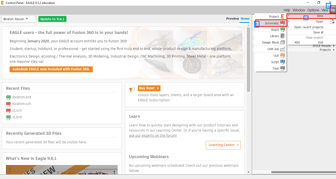
- First of all, I downloaded Autodesk Eagle and install it on the laptop, then download the fab library
- Opened Eagle
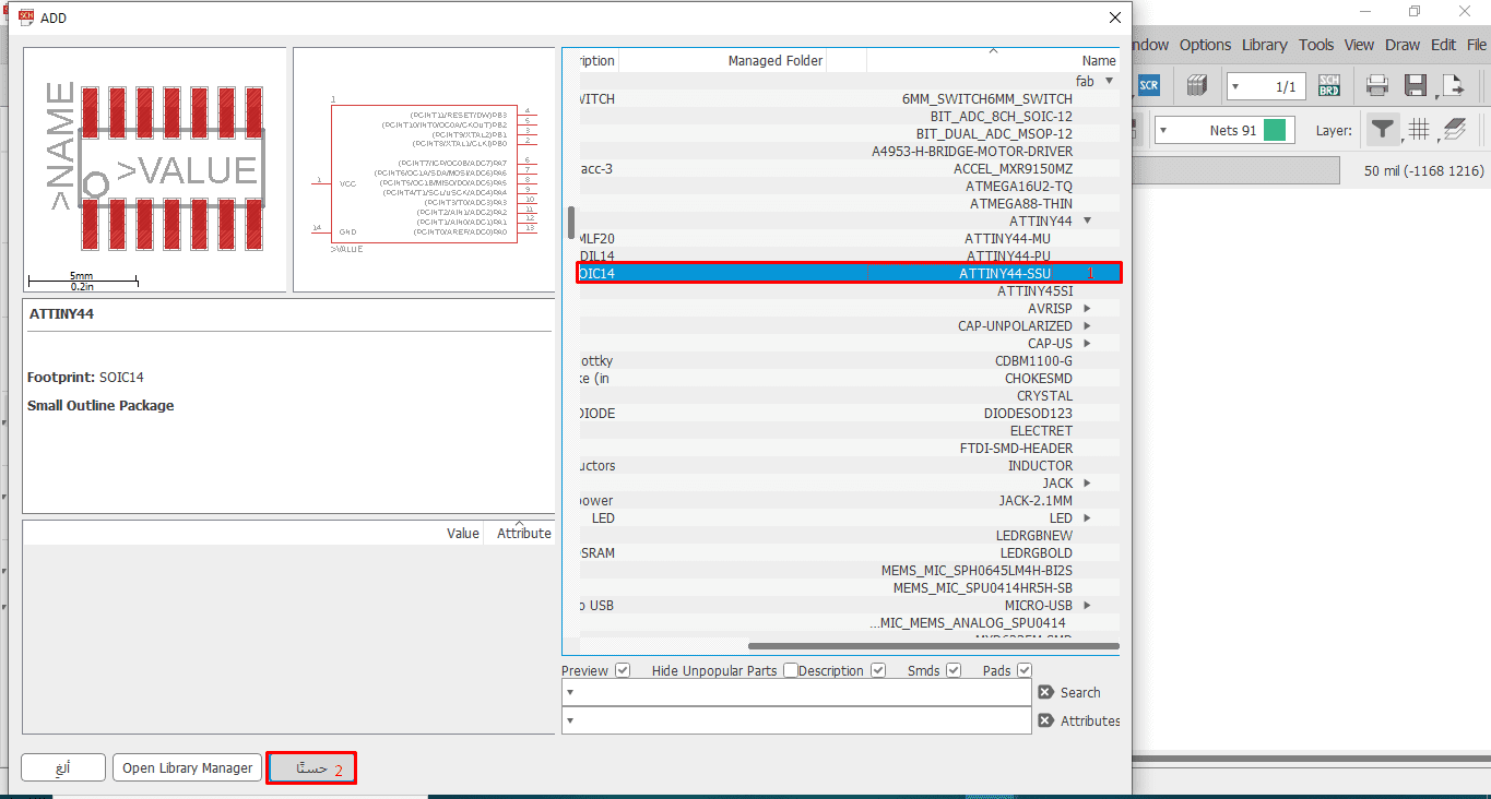
- Add fab library, make sure it is in use
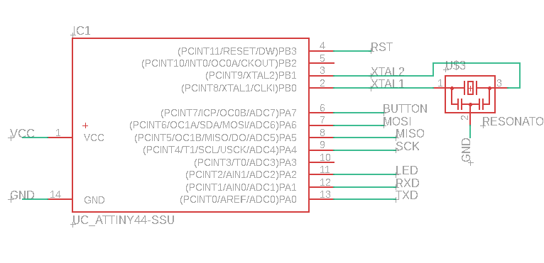
- Then I added my first component, ATTINY44-SSU
- Then I added the other pieces
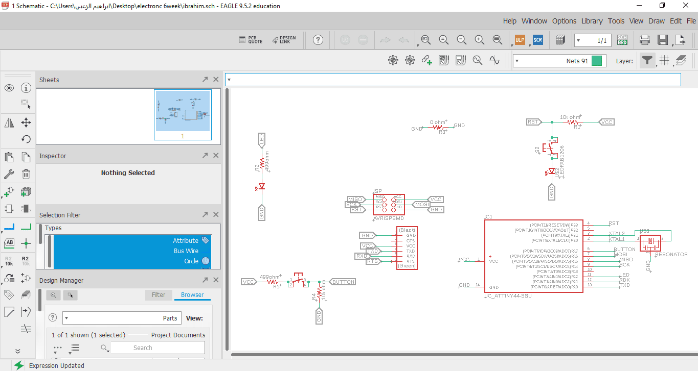
First, after opening Eagle and installing the library, I open schematic
The Components used in my board
| Components | The number |
|---|---|
First, I added my first component, ATTINY44-SSU
After adding it, I explained the work of some of the tools i need in my work as show in Picture
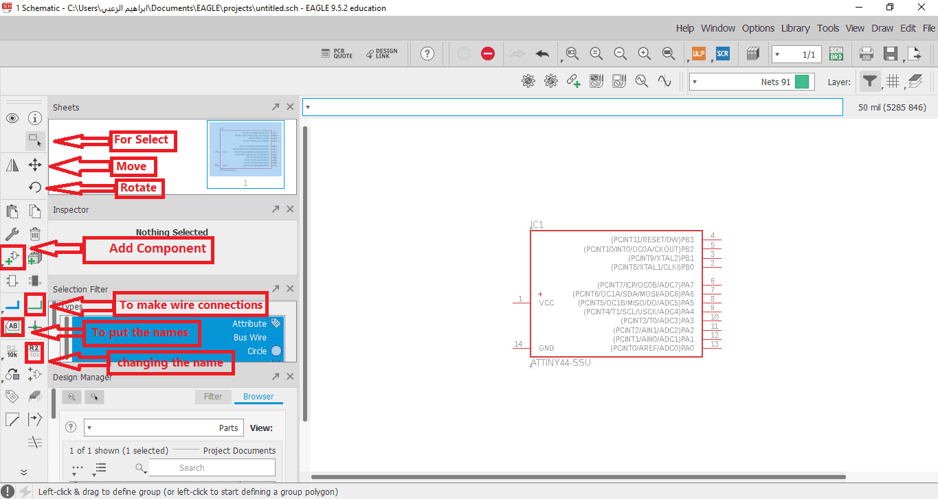
Also, be sure to plug the wires of each component and name it so that it is there Any error in communication

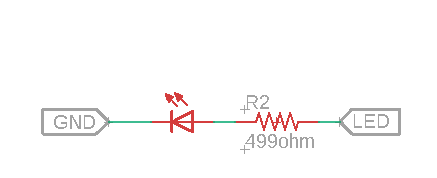
I also added a LED and connected it with pin number 11 , it will help me in the programming process later to make sure that the board works
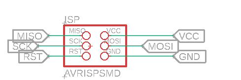
I added a 6 pin to work as a ISP programming board in c language
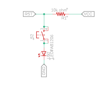
I also added an LED with a button to control it
Here, I have finished adding and connecting all parts
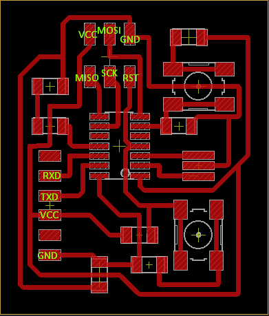
Board Design
for transference than Schematics to design board

All components are outside the black board

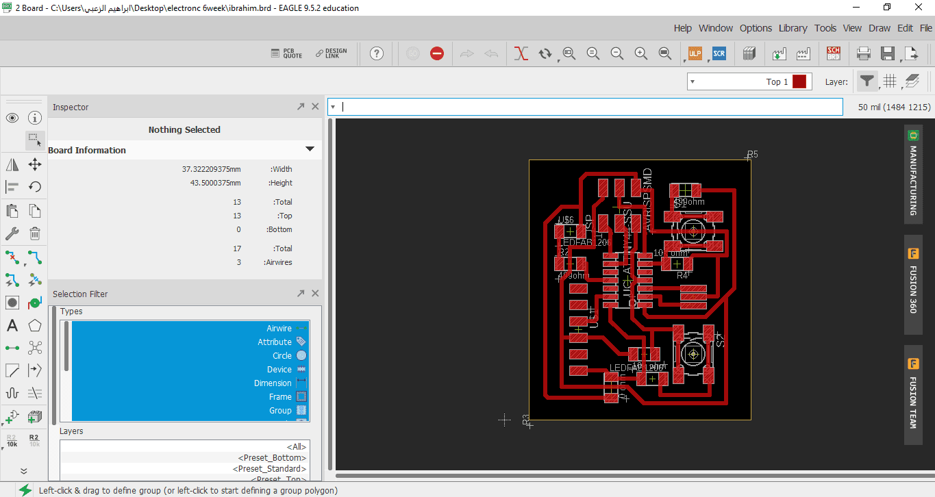
I transfer them into the blackboard and start Attiny44 then the rest of the pieces ,Using the "Route Airwire" option, I connect the parts together correctly,And from the drop-down menu as shown in the picture below, I can control the width of the connection line
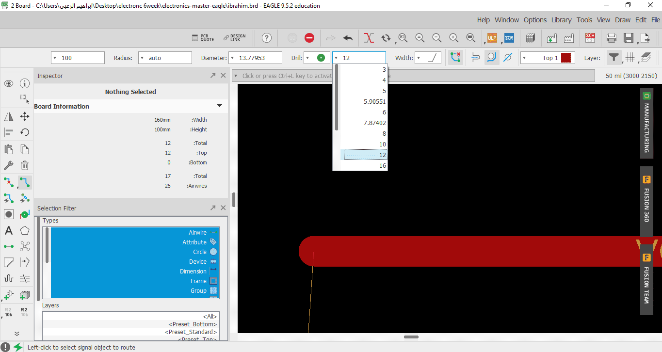
The time you have connected all the parts with us correctly as shown in the picture


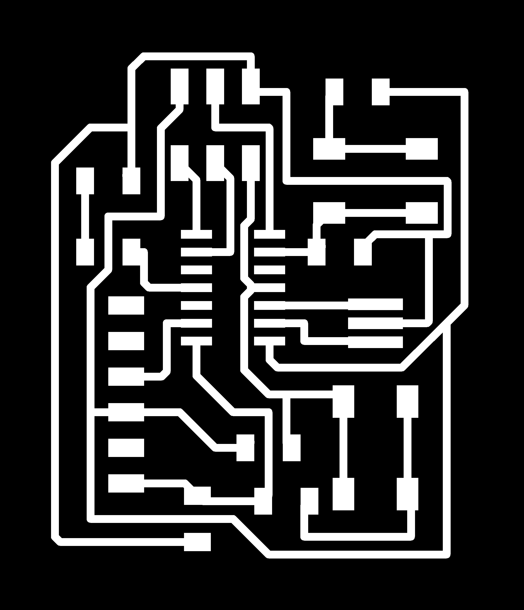

Fab modules
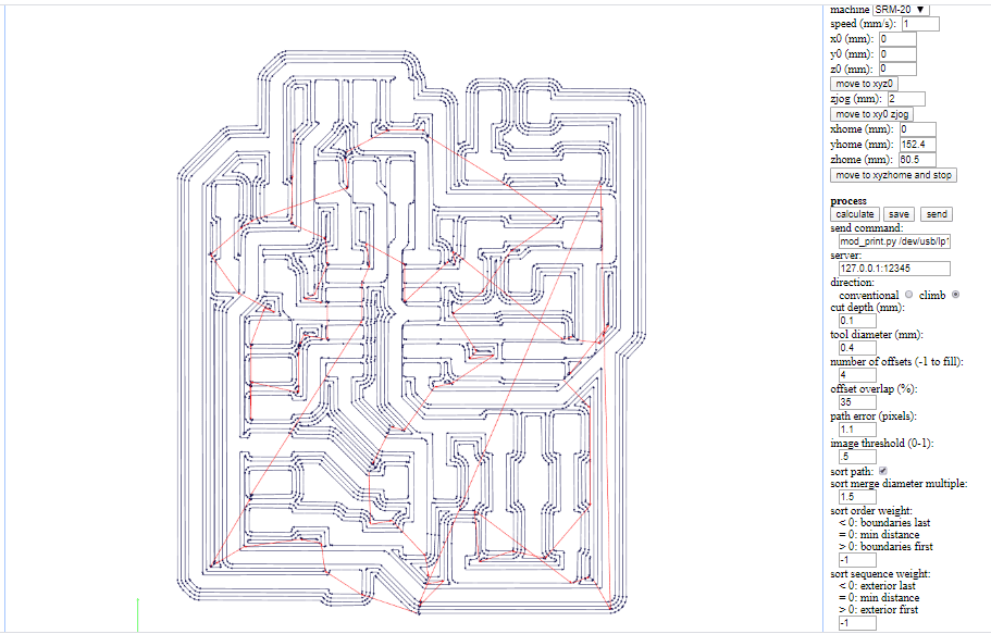
Then I inserted images into Fab Modules to set the settings for the embossing process as shown below.
The parts used in the electronic tablet
OutLine Settings
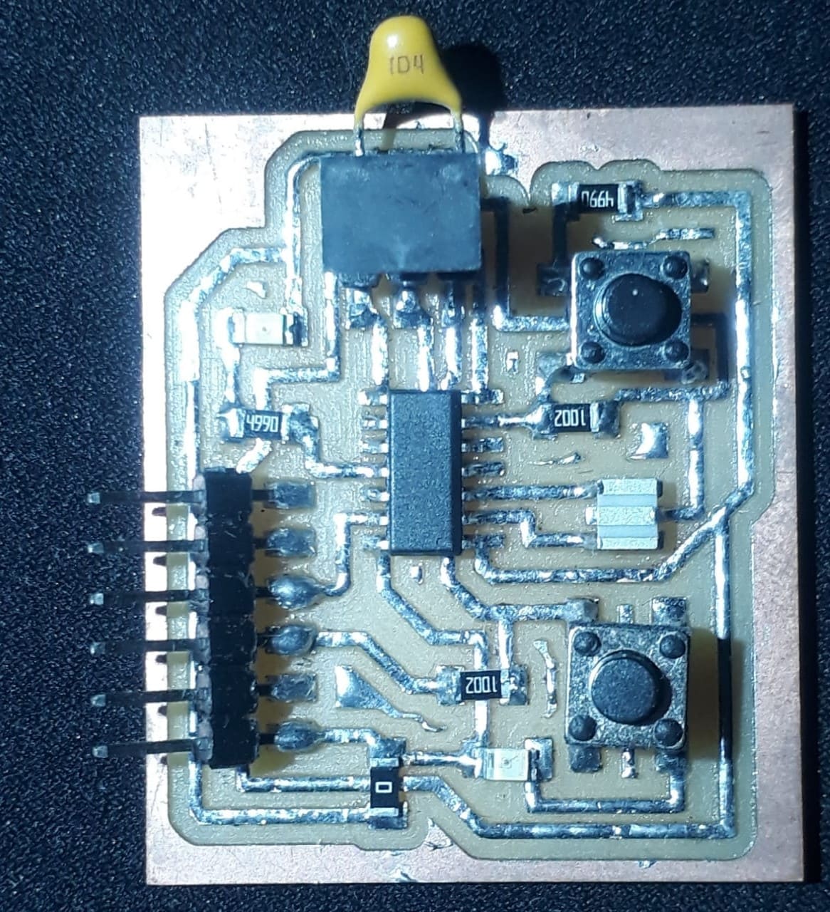
MILLING & SOLDERING
.jpg)
.jpg)
.jpg)
.jpg)
After that I started the welding process and installed all the components As shown in my design on the Eagle program
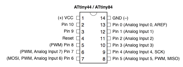
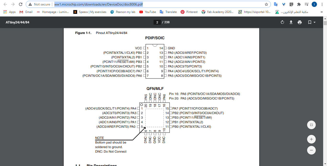
Datasheet ATTiny44 Datasheet
All of the electronic components must have a datasheet, that is a very extensive (generally) sheet of text that specifies every part of the component, from how to program it, to the general pins, and in the case of the microcontrollers, how to modify the clock inside the component.

The first part is very important to read is the pinout section. Must of the components have one. There it is specified what does every pin in the component means, so you can design a circuit around the microcontroller. For example, in the VCC I connected the positive end of the power supply, and on the GND the other end.
There is a block diagram in the datasheet that specifies every part inside the component. As you can imagine there is an entire world inside this tiny component.
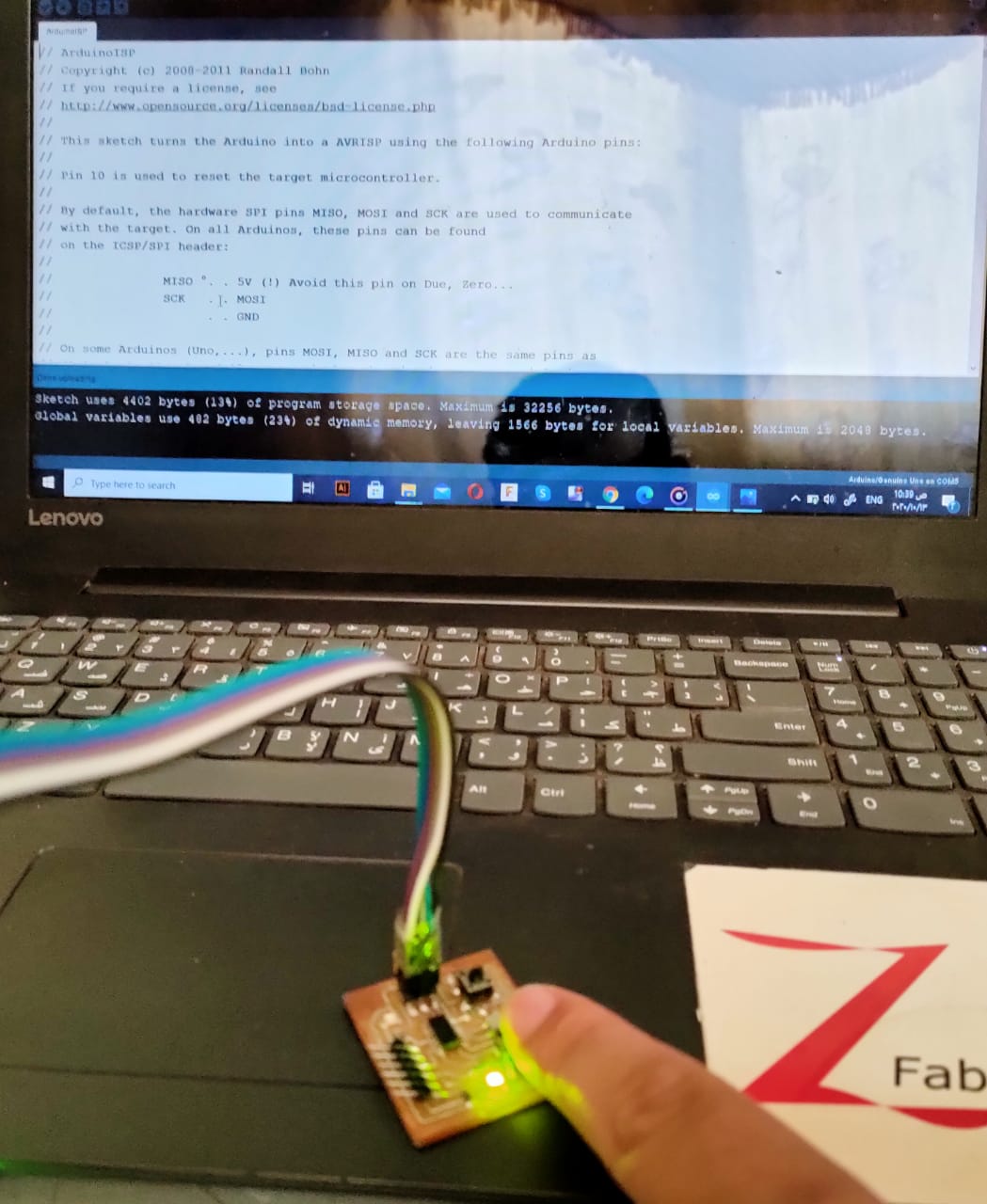
Programming the BoredBoard
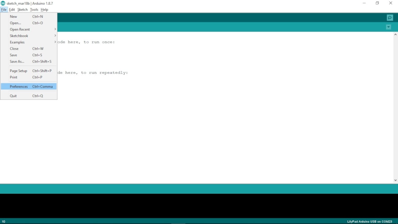
1- Go to File > Preferences
2- On the Preferences windows, on the Additional Boards Manager URLs section, paste the followed link (Note: if you have already a URL like I did, just write a "," at the end of the previous one and then paste the new one):
https://raw.githubusercontent.com/damellis/attiny/ide-1.6.x-boards-manager/package_damellis_attiny_index.json

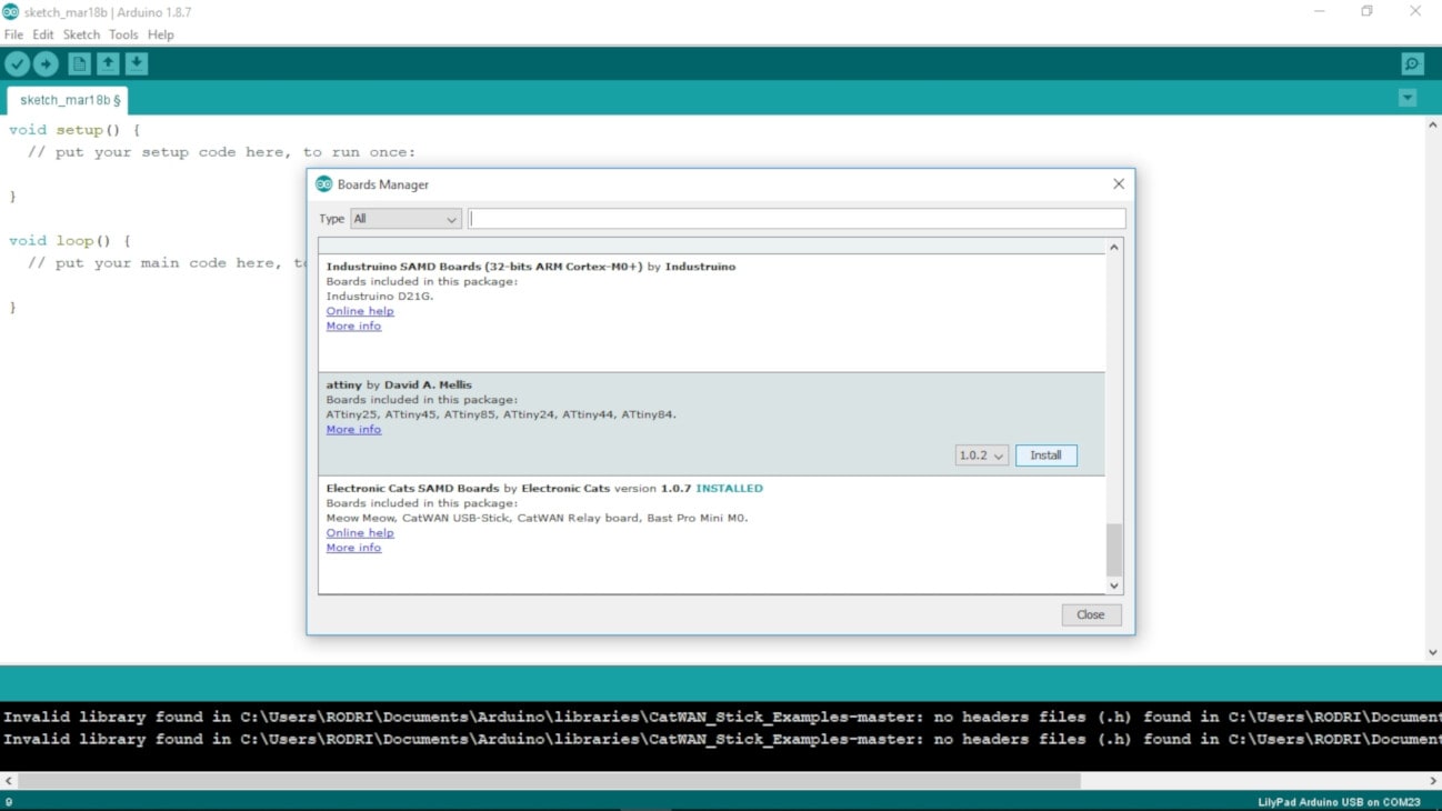
3- Go to Tools > Board > Boards Manager...

4- On the Boards Manager window, look for the "attiny" by David A. Mellis package, and click Install. Then close the window.
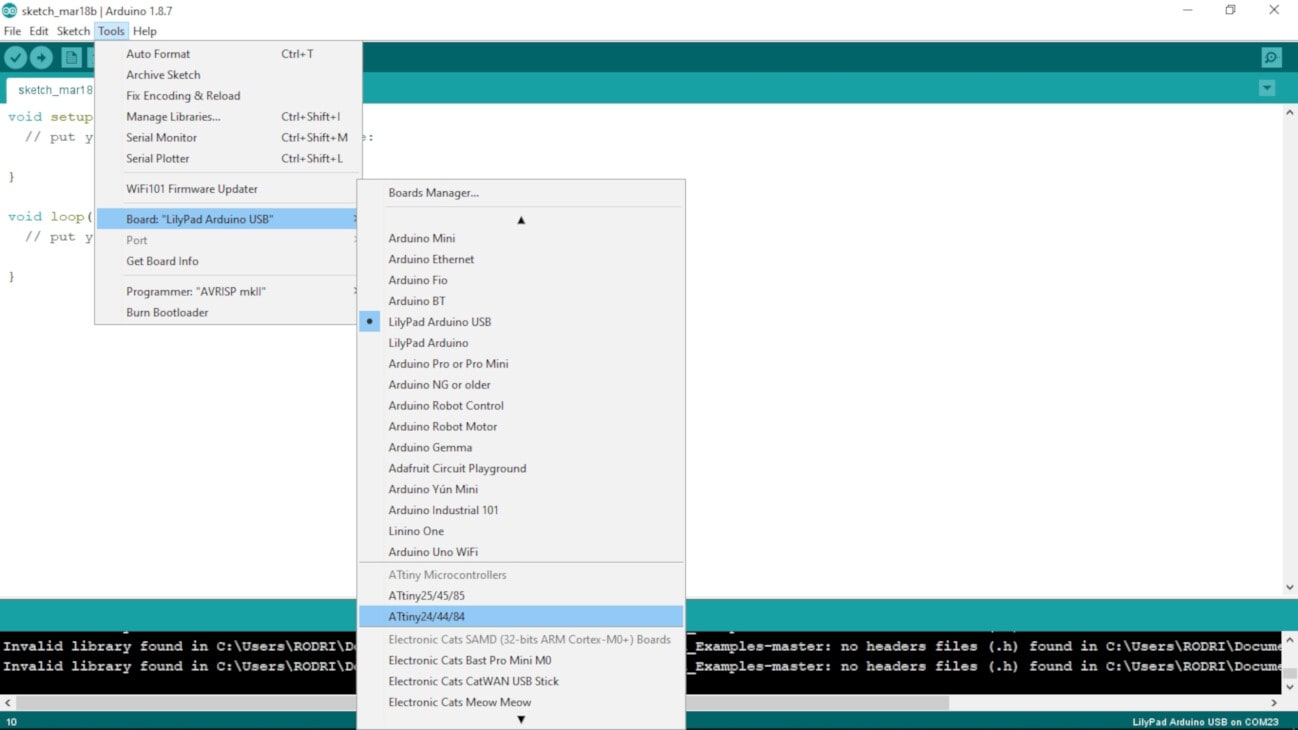
5-Go again to Tools > Board, and select the ATtiny24/44/84 under the ATtiny Microcontrollers section.
Connect the BoredBoard
For download my file and lib check here